Engineers use the control valve symbol to identify the type of control valve they want to specify for a particular application. In this article, we will identify the most commonly used control valve symbols.
WHAT IS A PIPING AND INSTRUMENTATION DIAGRAM (P&ID)?
Before a well is completed, the facilities engineer creates a diagram of all the pipes and instruments used to produce the well. This is called a "Piping and instrumentation Plan" and is often shortened to "P&ID".
Once P&ID is completed and approved, it will move to the purchasing department. The department is responsible for providing this information to various equipment suppliers, requesting quotations, and purchasing equipment for the well.
The supplier then manufactures, packages and ships the equipment to the production site. On site, production supervisors, foreman, leasing operators, and pump and rig personnel install equipment according to P&ID.
What are the types of valve symbols in P&ID?
Valve symbols on P&ID vary according to the type of valve specified for application. Each P&ID has its own legend, a symbol used to identify the various devices.
Although there are some variations, examples of the standard notation for valves are in the PDF below.
Symbols include:
- gate valve symbol
- globe valve symbol
- ball valve symbol
- plug valve symbol
- butterfly valve symbol
- diaphragm valve symbol
- check valve symbol
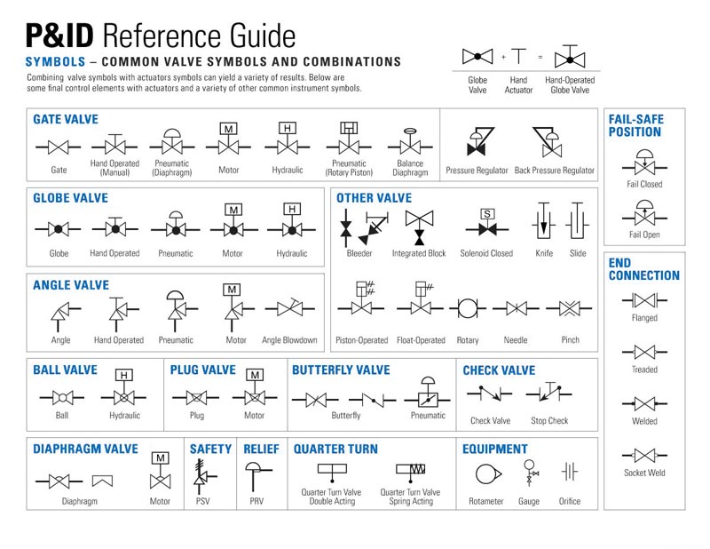
Engineers can also list specific details under the control valve symbol. These details may include valve size, function, pressure rating, and connection type. For example, note 2 "300 RF PB indicates that P&ID requires the valve to be a 2" ANSI 300 raised face piston balance valve.
