+86-18058825678
- All
- Product Name
- Product Keyword
- Product Model
- Product Summary
- Product Description
- Multi Field Search

- Home
- Our Product
- About Didtek
- Solutions
- Exhibition Show
- Support
- News
 English

Views: 0 Author: Site Editor Publish Time: 2026-09-12 Origin: Site


Industrial piping systems rely heavily on precise fluid control to maintain safe, efficient, and continuous operations. Selecting the wrong ball valve design often leads to fugitive emissions, excessive pressure drops, premature seat wear, and costly system downtime. These mechanical failures compromise worker safety and severely disrupt operational output. You must carefully match your piping system's unique requirements to the appropriate valve architecture to ensure optimal performance.
This guide provides an engineering-level evaluation framework to help you map specific parameters—such as pressure limits, media characteristics, and flow control needs—to the correct industrial valve type. You will learn exactly how structural designs, internal bore dimensions, and port configurations directly influence fluid dynamics. You will also discover how different body assembly styles impact your ongoing maintenance workflows. Before evaluating specialized construction materials and automated actuation methods, engineers must clearly define the foundational mechanical design of the valve to ensure long-term reliability.
Pressure & Size dictate the anchor: Floating designs serve low-to-medium pressure applications, while trunnion designs are mandatory for high-pressure and large-diameter piping.
Flow requirements dictate the bore: Full port designs eliminate pressure drops; standard ports offer cost savings where flow restriction is acceptable.
Maintenance dictates body style: 3-piece bodies allow in-line maintenance, which is critical for welded or high-uptime systems.
System routing dictates port count: Multi-port designs (like a three way ball valve) can replace multiple two-way valves to streamline piping layouts.
When evaluating the broad spectrum of ball valve types, determining the core structural design forms the foundation of your specification process. You face a critical binary choice right at the start. System pressure and pipeline diameter primarily dictate whether you need a floating or trunnion configuration. Making the wrong choice here severely impacts operational safety and mechanical longevity.
A floating ball valve operates on a remarkably simple but effective principle. The ball remains entirely suspended within the fluid media. When closed, upstream line pressure physically pushes the ball downstream against the soft seating ring. This mechanical action compresses the seat and creates a tight, bubble-tight seal. These valves excel in low-to-medium pressure systems. They perform exceptionally well for smaller pipeline diameters handling clean, non-abrasive media. However, they carry distinct mechanical limitations. As system pressures increase, the force pushing the ball into the seat rises exponentially. This creates immense friction, leading to high operating torque. Furthermore, sudden pressure spikes easily damage the soft seats, rendering the valve prone to leakage.
Conversely, a trunnion ball valve utilizes a fundamentally different sealing mechanism. The ball is mechanically anchored by solid shafts at both the top and bottom. Because the ball remains stationary on its axis, line pressure moves the spring-loaded upstream seats against the ball, rather than moving the ball itself. This structural design is absolutely mandatory for high-pressure applications, particularly those exceeding ASME Class 600. It is also essential for large-diameter pipelines where a floating ball would be too massive to operate efficiently. Trunnion mounts absorb massive pressure loads safely. They provide a much lower and highly predictable operating torque profile. This predictability makes them the ideal choice for systems requiring precise automated actuation.
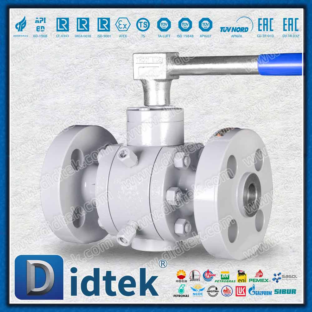
The internal diameter of a valve heavily influences system flow dynamics. We evaluate this dimension because it dictates total flow capacity, operational efficiency, and fluid velocity. Choosing the correct bore design ensures you do not inadvertently choke your pipeline or introduce unnecessary turbulence.
A full port ball valve features an internal bore that perfectly matches the connecting pipeline's inner diameter. This seamless structural choice delivers specific, measurable outcomes. It ensures zero flow restriction across the valve body. Consequently, it eliminates localized pressure drops entirely. This 1:1 ratio also grants operators the ability to run mechanical cleaning pigs or inspection tools through the line without obstruction. Engineers specify full port options primarily for slurries, highly viscous fluids, and critical flow applications requiring maximum unhindered throughput.
Standard or reduced port valves take a different approach. Their internal bore is typically one pipe size smaller than the connecting pipeline. This deliberate reduction decreases the physical footprint, weight, and manufacturing cost of the unit. The tradeoff involves increased pressure drops and the introduction of localized flow turbulence immediately downstream of the valve. These valves serve perfectly in general liquid and gas transport scenarios. You can deploy them safely in long piping runs where a minor flow restriction does not negatively impact overall system efficiency.
Complex piping architectures often require engineers to mix distinct media streams or divert flows to different processing tanks. Traditional layouts achieve this by combining multiple isolation valves into intricate, hard-to-maintain automation loops. Selecting multi-port configurations directly simplifies these engineering challenges.
Two-way valves represent the standard industrial approach. They provide basic on/off isolation through a single inlet and a single outlet. They form the straightforward backbone of most fluid control networks, allowing media to travel in a straight line.
When system routing grows complex, integrating a three way ball valve becomes highly advantageous. These units replace multiple standard valves, reducing potential leak points and saving valuable spatial footprint. They utilize two distinct internal geometries:
L-Port (Diverting): This internal configuration directs flow from one common inlet into one of two separate outlets. A 90-degree turn of the handle shifts the flow path entirely while isolating the previously used port.
T-Port (Mixing/Selecting): This design offers far more versatility. It can mix two separate inlet streams into a single common outlet. Alternatively, it can allow straight-through flow between two opposing ports while completely shutting off the third perpendicular port.
Implementation of multi-port designs carries specific operational risks. You must program pneumatic or electric actuators precisely. Poor alignment during the transitional phases of rotation can cause temporary cross-contamination between streams. It can also lead to unintended deadheading, where fluid pressure spikes dangerously because all ports are momentarily blocked.
Valve housing designs directly influence field installation methods and lifecycle maintenance workflows. The body assembly style determines how easily maintenance teams can access internal components when soft seats eventually wear out. Evaluating this dimension requires understanding your facility's tolerance for system downtime.
Different housing configurations offer distinct structural profiles and implementation realities:
1-Piece Body: This design features a solid, unified cast construction. It almost always contains a reduced bore to fit the internal components through a smaller opening. It offers the lowest initial purchase cost. However, the implementation consideration is stark: it is entirely non-repairable. Facilities treat it as a throwaway component upon failure.
2-Piece Body: This represents the standard industrial configuration. It splits the housing into two sections bolted or threaded together. To replace worn seats or damaged balls, maintenance teams must physically remove the entire unit from the pipeline. It works best for flanged or threaded systems where offline maintenance remains operationally feasible.
3-Piece Body: This highly robust design features a center section housing the ball and seats, flanked by two separate end caps. The end caps remain securely attached to the adjacent pipe. During maintenance, technicians simply remove a few bolts, and the center section swings out for immediate service. This implementation is absolutely mandatory for welded piping systems. It allows rapid, in-line seal replacement without ever cutting the pipe, vastly reducing critical downtime.
Engineers must integrate structural body types with specific metallurgical choices and secure connections. This comprehensive decision framework finalizes the valve specification. When exploring various types of ball valves, mapping these three dimensions properly ensures reliable long-term performance under demanding conditions.
Title: Valve Material and Connection Matrix
Specification Category | Option Profile | Implementation Reality & Use Cases |
|---|---|---|
Material: Carbon Steel | High tensile strength and heat tolerance. | Petrochemical processing and high-pressure oil refineries. Susceptible to internal rust if unprotected. |
Material: Stainless Steel (316/304) | Exceptional resistance to localized pitting and chemical attack. | Chemical manufacturing, pharmaceutical plants, and food processing facilities requiring strict hygiene. |
Material: Brass/Bronze | Cost-effective, easily machinable alloys. | Commercial water loops, standard HVAC systems, and low-pressure air lines. Not suited for highly corrosive media. |
Connection: Flanged Ends | Bolted face-to-face joints utilizing gaskets. | High-pressure industrial pipelines. Facilitates extremely easy removal during major plant turnarounds. |
Connection: Threaded (NPT) | Tapered pipe threads sealing through mechanical deformation. | Smaller pipeline diameters (under 2 inches). Dominates standard commercial and light industrial utility use. |
Connection: Socket/Butt Weld | Permanent fusion of the valve body to the pipe. | Critical zero-leak environments. Pairs exclusively with 3-piece bodies to prevent heat damage to soft seats during installation. |
Material selection relies entirely on media compatibility and environmental factors. Carbon steel tackles extreme pressure and high heat effectively. Stainless steel withstands harsh corrosives and maintains purity. Brass serves low-pressure utility water loops perfectly.
End connections must reflect actual installation realities on the factory floor. Flanged joints dominate heavy industrial sites because they handle massive stress and allow rapid replacement. Threaded connections fit standard commercial applications where welding poses a fire risk. Welded ends satisfy absolute zero-leak requirements but demand 3-piece valve bodies to ensure future maintenance remains possible.
Industrial flow control demands strict, unyielding adherence to authoritative engineering standards. You must ensure all specified valves meet relevant API and ASME codes. API 608 and API 6D govern the mechanical performance and testing of heavy-duty pipeline valves. ASME B16.34 dictates critical pressure-temperature ratings based specifically on the shell material thickness and composition. Ignoring these standards invites catastrophic failures.
Fire-safe design represents a major safety requirement in hydrocarbon processing. Engineers must specify API 607 compliant valves for any flammable media applications. These specialized units feature a dual-seating architecture. During normal operation, the ball seals against primary PTFE or TFM soft seats. If an external fire elevates temperatures enough to melt these polymeric seats, the ball shifts slightly downstream. It then engages a secondary machined metal seat. This metal-to-metal contact establishes an emergency seal, preventing massive leaks that would otherwise fuel the fire.
Fugitive emissions pose another significant regulatory and implementation risk. Modern environmental regulations require rigorous evaluation of stem packing designs. Standard packing glands often loosen due to thermal cycling and mechanical wear, allowing invisible toxic gases to escape. Advanced designs utilizing live-loaded Belleville washers solve this issue. These conical spring washers maintain constant, dynamic pressure on the packing materials even as they wear down over thousands of cycles. This engineering upgrade helps facilities confidently meet strict ISO 15848 or EPA standards for hazardous gas containment.
Selecting the ideal valve architecture requires a highly methodical and disciplined approach. Base your initial filter on pressure limits and pipe size to determine whether a floating or trunnion anchor is appropriate. Follow this by analyzing your fluid dynamics to decide if a full or standard port best supports your process. Finally, assess your facility's long-term maintenance needs to finalize the correct body style configuration.
We strongly advise engineers, pipe fitters, and procurement teams to consult directly with a certified valve specialist or application engineer. Bring complete system data to this conversation, including the specific media chemistry, maximum operating pressure, and peak temperature parameters. Taking this crucial next step ensures accurate sizing, verifies chemical compatibility, and precisely dials in any pneumatic or electric actuation requirements prior to installation.
A: The primary difference lies in the internal anchoring mechanism. A floating ball suspends directly in the fluid media, relying entirely on upstream line pressure to push it against the downstream seat for sealing. Conversely, a trunnion ball is mechanically anchored by solid shafts at the top and bottom. Line pressure pushes spring-loaded seats against the stationary ball. This anchored design is critical for safely managing high-pressure and large-diameter applications.
A: Generally, no. Standard designs exist strictly for on/off isolation duties. Using them for throttling exposes their soft polymeric seats to high-velocity flow. This creates rapid erosion, localized pressure drops, and permanent seat damage, leading to internal leakage. However, specialized V-port ball valves feature uniquely contoured balls designed specifically to modulate flow safely without damaging the sealing surfaces.
A: A full port design means the internal bore diameter of the valve matches the exact inner diameter of the connecting pipeline. This perfect 1:1 ratio ensures there is zero flow restriction and zero pressure drop as fluid passes through. It also allows maintenance teams to run mechanical cleaning pigs or inspection tools straight through the pipeline without encountering any structural obstruction.
A: End connections depend directly on your pipeline material, system pressure rating, and future maintenance access needs. Use simple threaded connections for small commercial lines. Specify bolted flanged ends for high-pressure industrial systems that require secure sealing but easy future removal. Choose welded connections for permanent, high-vibration, zero-leak environments, always pairing them with 3-piece bodies for vital maintenance access.


