+86-18058825678
- All
- Product Name
- Product Keyword
- Product Model
- Product Summary
- Product Description
- Multi Field Search

- Home
- Our Product
- About Didtek
- Solutions
- Exhibition Show
- Support
- News
 English

Views: 0 Author: Site Editor Publish Time: 2026-09-12 Origin: Site


Reliable fluid control ensures system integrity and workplace safety. It also heavily drives process efficiency across industrial applications. Unreliable shut-off mechanisms routinely cause dangerous leaks. They create sudden pressure drops and often trigger costly operational downtime. You need a highly dependable solution to maintain seamless operations. Industry experts rely heavily on these specific quarter-turn mechanisms for tight shut-offs. We consider them the absolute gold standard for robust flow management across various sectors. Transitioning from basic component concepts to deep evaluation helps everyone. Engineers and procurement teams can properly assess their specific compliance needs. You will discover exactly how these core components operate daily. We will explore their internal construction and their most critical applications. You will learn to match specific structural designs to your most demanding system requirements. This guide provides actionable insights for optimizing your pipeline architecture today.
Mechanics: Ball valves utilize a hollow, pivoting sphere (the ball) to control fluid flow, requiring only a 90-degree turn to fully open or close.
Core Advantage: They offer a bubble-tight seal with minimal pressure drop, making them ideal for critical shut-off applications rather than fine flow modulation.
Status Verification: An operator can instantly tell if a ball valve is open or closed by observing the handle's alignment relative to the pipe.
Selection Variables: Choosing the right valve requires evaluating port size, seat materials, and mounting styles (floating vs. trunnion) against specific temperature and pressure parameters.
To master industrial pipeline design, you must first understand the underlying principles of flow control. When operators ask how do ball valves work, they look for a simple mechanical explanation. The valve operates using a highly effective rotational mechanism. A hollow sphere sits inside the valve body. We call this component the rotary ball. A central bore runs directly through it. You open the flow path by aligning this hollow bore with the connecting pipeline. Media flows through the center freely. You block the flow by pivoting the sphere exactly 90 degrees. The solid side of the sphere instantly blocks the fluid path.
This simple quarter-turn mechanism delivers specific operational outcomes. It defines why facilities choose these components over multi-turn alternatives.
Quarter-Turn Actuation: Operators can actuate the mechanism rapidly. You can isolate hazardous fluids instantly during emergency shut-down scenarios. This speed prevents catastrophic facility accidents.
Straight-Through Flow: The aligned bore creates a completely unobstructed pathway. It drastically reduces internal fluid turbulence. This design eliminates fluid friction and optimizes overall system efficiency.
The fundamental operating principle remains perfectly consistent across different automation strategies. Manual levers provide simple human control for accessible pipelines. Pneumatic actuators utilize compressed air to turn the stem in hazardous environments. Electrical actuators use motorized systems for precise remote control. Regardless of the chosen actuation method, the internal sphere still relies on a simple 90-degree rotation.
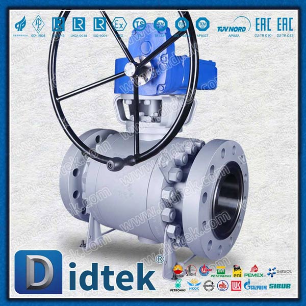
You cannot specify pipeline hardware without evaluating its individual components. Examining this internal anatomy reveals exactly what drives the ball valve function under extreme stress.
The valve body acts as the primary pressure vessel. It contains the internal fluid and withstands immense structural forces. Material selection directly impacts long-term durability and safety. Engineers select carbon steel for high-pressure industrial environments. They specify stainless steel to combat harsh chemical corrosives. Commercial plumbing systems frequently utilize brass or PVC materials for standard water distribution.
The rotary ball serves as the primary flow control element. Manufacturers must machine this sphere to exacting tolerances. The surface finish dictates the longevity of the internal seal. A highly polished sphere prevents premature friction wear. Scratches on the ball surface will ultimately compromise the tight fluid seal.
Seats act as the vital seal rings inside the housing. They press firmly against the rotary ball. Most general applications use soft materials like PTFE or PEEK. Soft seats offer excellent bubble-tight sealing capabilities. However, they present a distinct operational risk. Soft seats remain highly vulnerable to abrasive media. Solid particulates can easily tear soft materials. High-temperature applications often require rugged metal seats instead.
The stem and packing assembly connects the external actuator to the internal ball. This shaft transfers the rotational force. You must always insist on blowout-proof stem designs. A blowout-proof stem loads from the inside of the valve body. Internal pipeline pressure physically pushes the stem upward into a retaining shoulder. This design acts as a non-negotiable safety feature. It prevents the stem from ejecting outward under extreme pressure spikes.
Table 1: Common Housing Materials and Application Strengths
Material Category | Primary Industrial Application | Key Performance Strength |
|---|---|---|
Carbon Steel | Oil & Gas, High-Pressure Lines | Exceptional tensile strength and pressure resistance. |
Stainless Steel | Chemical Processing, Food & Beverage | Superior resistance to oxidation and harsh corrosives. |
Brass | Commercial Water Systems, HVAC | Excellent workability and basic water corrosion resistance. |
PVC / CPVC | Low-Pressure Chemical, Irrigation | Lightweight and entirely immune to galvanic corrosion. |
Visual verification remains a critical safety protocol in modern industrial environments. Maintenance crews must identify fluid flow status immediately. A simple glance can prevent accidental fluid discharge during routine maintenance. Technicians frequently need to determine if a ball valve open or closed state currently exists on the line.
Manual indicator rules provide foolproof visual confirmation. The exterior handle attaches directly in line with the internal hollow bore. When the handle sits completely parallel to the pipe, the valve is OPEN. Fluid flows freely through the system. When an operator turns the handle perpendicular to the pipe, the valve is CLOSED. This cross-pipe orientation visually signals a blocked fluid path.
Unstaffed or remote pipelines require entirely different verification strategies. Operators cannot walk the pipeline to inspect handles manually. Facilities solve this by implementing automated system verification. Engineers install limit switches and sophisticated position indicators directly on the actuator. These electronic devices detect the exact physical position of the stem. They feed real-time telemetry back to a central SCADA control system. Control room operators can instantly verify flow status on their digital dashboards without conducting physical field inspections.
No single design fits every industrial application perfectly. Specifying a reliable quarter turn ball valve requires carefully matching structural configurations to your system demands.
Port sizing decisions heavily influence both system efficiency and overall weight. You must evaluate the bore diameter relative to the connecting pipe. Full port designs feature a bore diameter identical to the pipeline. They offer zero flow restriction. This configuration proves ideal for pipelines requiring routine "pigging" operations for cleaning or inspection. However, full port models remain bulkier and demand heavier structural supports. Standard or reduced port models feature a bore one size smaller than the pipe. They provide a cost-effective alternative. You should select reduced ports for applications where a slight pressure drop remains acceptable.
Structural approaches dictate how the internal components handle line pressure. You must choose between floating and anchored configurations based on operational scale.
Floating Ball Design: The internal ball is not rigidly anchored to the stem. Upstream line pressure physically pushes the sphere against the downstream seat. This mechanical action creates the seal. We recommend floating designs primarily for low-to-medium pressure systems.
Trunnion Mounted Design: Large diameter pipes and high-pressure scenarios generate immense thrust forces. A floating design would crush the downstream soft seat under these conditions. Trunnion designs anchor the ball securely at the top and bottom. The line pressure pushes the floating seats against the stationary ball instead. This design prevents excessive operating torque and eliminates severe seat damage.
Understanding how does a ball valve work also means recognizing its mechanical limitations. Proper implementation requires strict adherence to established engineering constraints.
You must know precisely when NOT to use this specific hardware. Throttling represents the most common application error. You should never use a standard quarter-turn mechanism for fine flow modulation. Leaving the sphere partially open exposes the delicate soft seats to high-velocity fluid flow. This localized velocity causes severe cavitation and rapid erosion. The seat material degrades quickly. This misuse leads directly to premature operational failure. Furthermore, you should avoid using them for slurries or heavy particulates. Solid particles easily get trapped inside the internal body cavity behind the sphere. The accumulated debris will eventually seize the rotational movement completely.
Engineers evaluate multiple dimensions before approving a final specification. Follow these specific evaluation criteria to ensure system reliability:
Pressure-Temperature (P-T) Rating Analysis: Soft sealing materials lose their mechanical strength as temperatures rise. You must learn to read manufacturer P-T charts carefully. A component might handle high pressure at room temperature but fail catastrophically at 300 degrees Fahrenheit. Always map your extreme operational parameters against the official P-T curve.
Industry Compliance Certification: You must verify structural integrity through recognized standards. Standard industrial applications typically require ASME B16.34 compliance. The Oil & Gas sector demands stricter API 608 or API 6D certifications. These certifications guarantee rigorous testing protocols and proven metallurgical quality.
Actuator Torque Sizing: You must calculate the exact breakaway torque required to turn the stem under maximum differential pressure. An undersized automated actuator will stall during an emergency shutdown. Always apply a generous safety factor to your torque calculations.
The quarter-turn mechanism provides an exceptionally reliable solution for industrial fluid isolation. While the foundational mechanics appear wonderfully simple, successful implementation remains complex. Specifying the correct internal construction requires careful consideration of system pressure, flowing media, and ambient temperature extremes. You must match body materials, port sizes, and mounting structures to your unique operational environment. Ignoring P-T ratings or using soft seats for abrasive slurries will compromise your pipeline integrity.
Take proactive steps to secure your facility's fluid control architecture. Audit your current pipeline systems to identify incorrectly applied throttling mechanisms. Consult a qualified process engineer to verify your port sizing and actuator torque calculations. Review detailed manufacturer specification sheets immediately to begin shortlisting properly certified vendors for your next facility upgrade.
A: Generally, no. They are designed strictly for on/off service. Throttling exposes the internal components to high-velocity fluid flow. This damages the soft seats and compromises the bubble-tight seal. Exceptions do exist for specialized V-port models engineered specifically for modulation.
A: Leaks are typically caused by heavily scored seats from solid debris in the line. They also result from the thermal degradation of PTFE seals due to over-temperature operations. In automated systems, inadequate actuator torque failing to complete the full 90-degree rotation often causes minor leakage.
A: Ball valves offer a very fast, 90-degree quarter-turn operation and excellent tight sealing. Gate valves require multiple manual turns, resulting in much slower operation. However, gate valves are often cheaper for large-diameter, low-cycle applications where emergency actuation speed is not required.


